Introduction
Last blog post on Firmware Extraction With CH341A - Tapo C220 described one possible way to dump firmware using a chip-off-extraction technique. However, the squashfs shown only contained part of the filesystem, as the other rootfs partition is encrypted.
UART Overview
UART stands for Universal Asynchronous Receiver/Transmitter and uses three lines: GND, RX (Read Line), and TX (Transmission Line). It operates without a clock, relying on baud rate, which is the speed of data transmission and can vary depending on implementation. In IoT devices, UART typically operates at 3.3 volts, and the TX line can be identified with a multimeter by detecting a floating voltage during data transmission, most visible at device boot when transmission is frequent.
Rootfs Decrytion Process
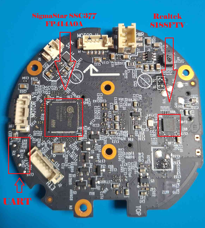
To start this process, the first thing to do is connect to the UART pads, identified in the following image, to get a shell on the device.
But there is a problem, that if we try to connect to it directly, no data is seen being transmitted. By examining the pads under a microscope, it is possible to notice that the board has traces with a missing connector, as shown inside the yellow circle in the following picture.
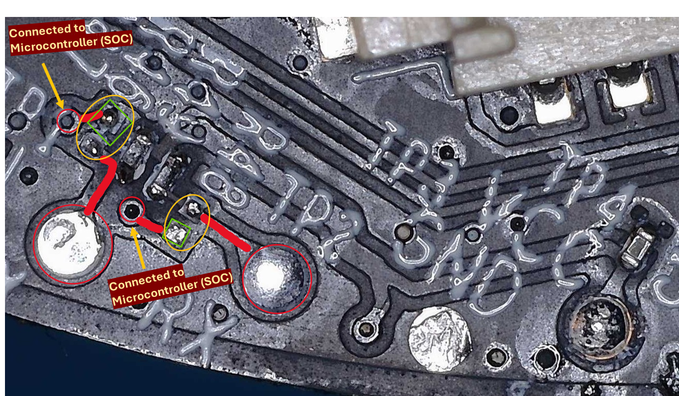
To connect to the shell, there are a few possible options, but in my case, I connected 3 PCBite probes to the green squares from the previous image, as data still reaches that point. Other options would be to solder the missing connector, solder cables to the green squares, or to connect directly to the SOC UART pins, which would require following the traces or checking the datasheet to verify which are the correct pins.
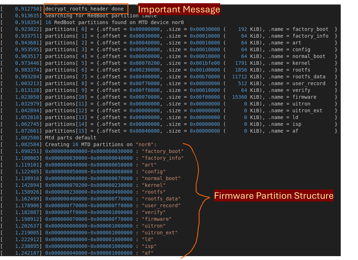
Then, connecting to the USB to TTL serial converter and using minicom, it is possible to see the data being transmitted. With access to the shell, it is noticeable that the TapoC220 camera prints a lot of information, which includes the firmware partition structure and the phrase decrypt_rootfs_header done, as shown in the following image.
The next step would be to identify which file contains the decrypt rootfs message, with the following command.

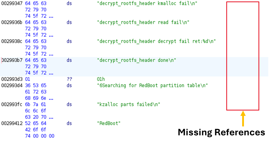
The binary can now be loaded into Ghidra with the correct CPU architecture, in this case ARMv7 little-endian, found through the UART logs. As seen in the following image, the strings are not linked to any function, which is demonstrated by the missing XREF in front of them.
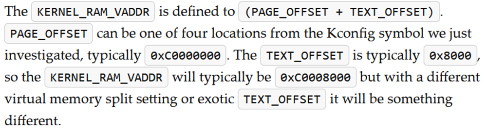
These missing references occur due to an incorrect base address passed to Ghidra when loading the binary. To find the correct base address, there are two options. First one is to go and read about the ARM kernel and understand how it starts and where it is loaded, which the linusw blog post explains in detail, as seen in the following image.
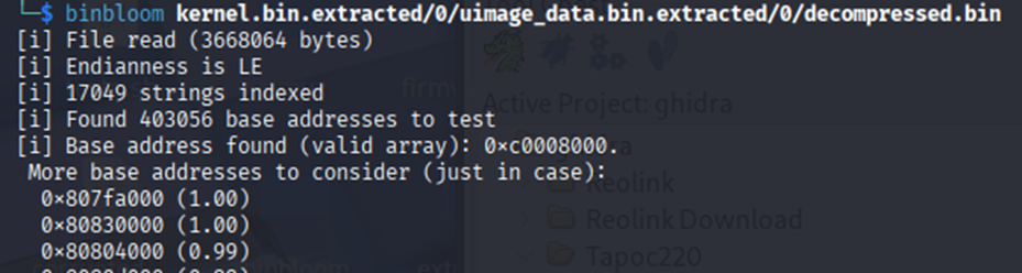
Another option is to use a tool such as Binbloom, which analyzes binary strings to determine the base address and endianness. As shown in the following image, it yields the same result.
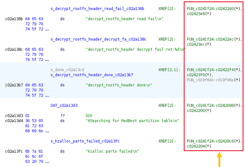
After loading the binary into Ghidra with the ARMv7 little-endian architecture and setting the base address to 0xC0008000, the strings are now correctly mapped to their corresponding functions.
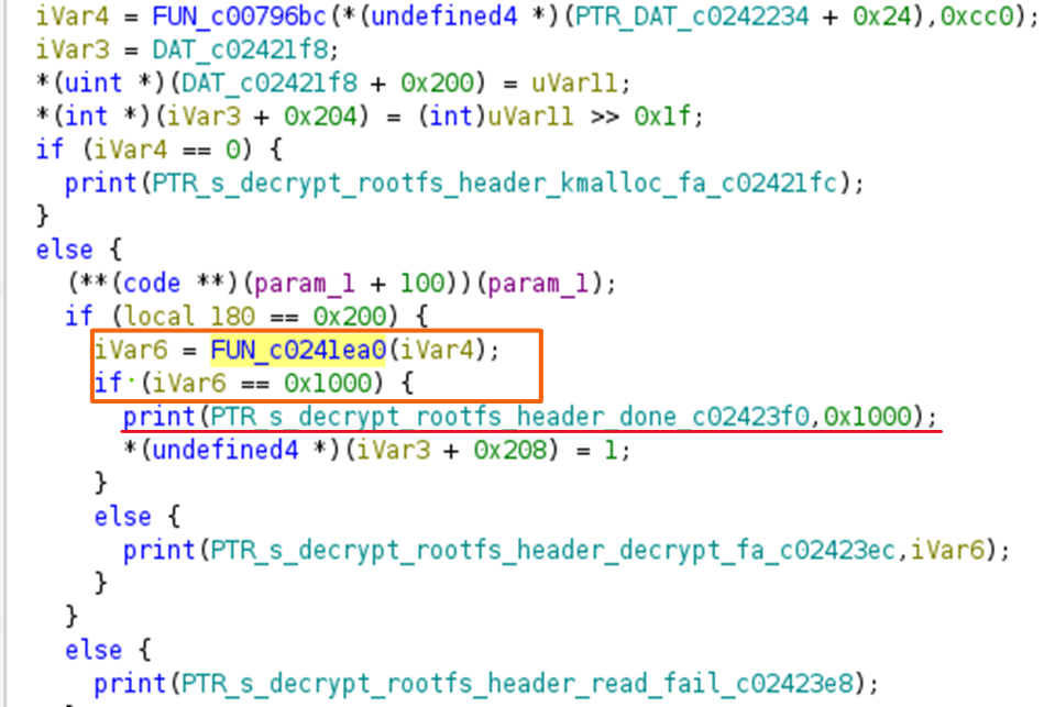
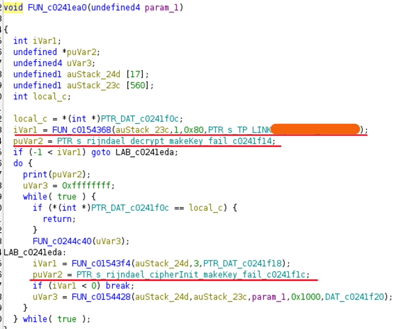
Double clicking on one of the references, it’s possible to see the following decompiled code where the string is being printed depending on the result of ivar6, which is assigned by the return value from FUN_c02411ea0.
Opening that function results in the code shown in the following image. Here, references to rijndael, which is associated with AES, and functions such as decrypt and cipherInit can be seen. Furthermore, a string starting with TP_LINK is also present.
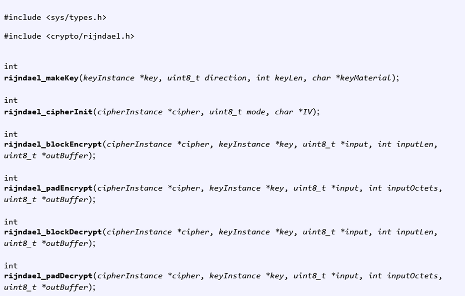
Searching for rijndael and makeKey online leads to the following code definition.
Renaming the function and variables resulted in the restructured function shown in the following image. From it, it is possible to understand which is the defined key, IV, and decryption mode. Furthermore, it is also possible to realize that only 4096 bits are being decrypted, which corresponds to 512 bytes.
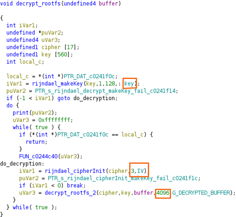
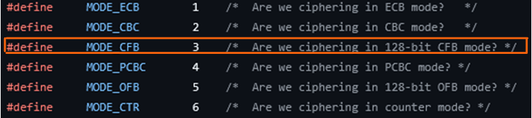
Now knowing the key, IV, how many bytes are encrypted, and that the operation mode is 3, the only thing left to understand is what precisely the operation mode 3 corresponds to, which, by looking online, is possible to see it corresponds to AES CFB 128-bit mode.
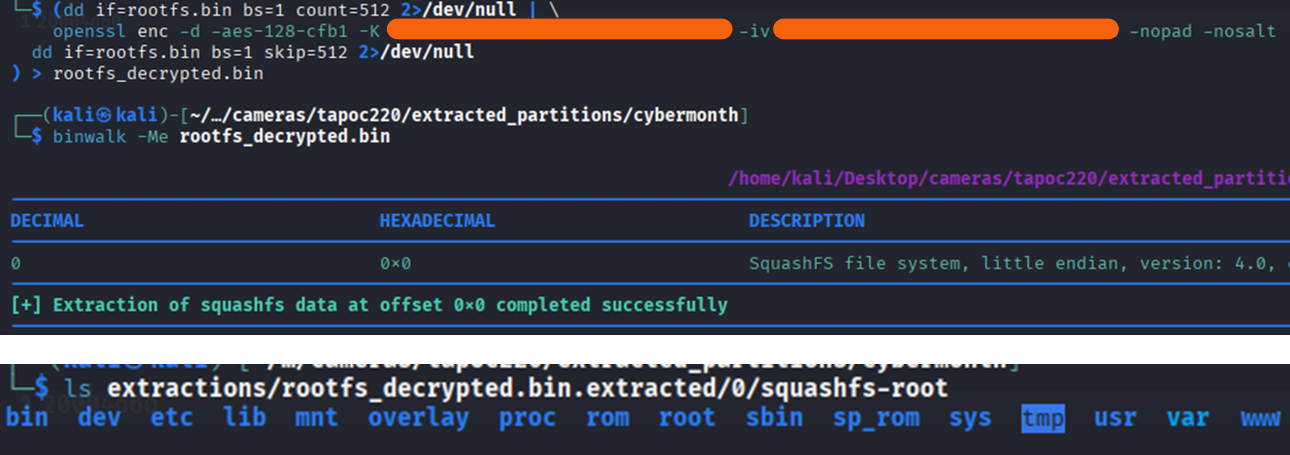
With all the information, the command (dd if=rootfs.bin bs=1 count=512 2>/dev/null | openssl enc -d -aes-128-cfb1 -K <key> -iv <iv> -nopad -nosalt; dd if=rootfs.bin bs=1 skip=512 2>/dev/null) > rootfs_decrypted.bin can be executed, giving the decrypted rootfs. This can then be extracted as shown in the following image.
Conclusion
This was a good opportunity to learn and review some core concepts of serial communication, reverse engineering, and electronics.
Best regards,
Diogo